Does Blender Work Like SolidWorks? A Practical CAD Comparison
An analytical comparison of Blender and SolidWorks for CAD and 3D modeling, covering purpose, workflows, tolerances, interoperability, licensing, and real-world use cases for home makers and engineers.

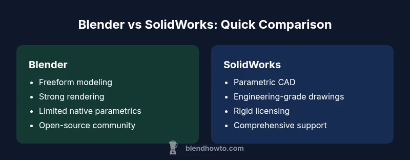
Blender and SolidWorks serve different purposes. Does blender work like solidworks? Not exactly. Blender is a versatile, open-source 3D tool for freeform modeling, sculpting, animation, and visualization, while SolidWorks is a parametric CAD system designed for engineering-grade parts, assemblies, and manufacturing documentation. For engineering production, SolidWorks generally wins; for concepting, mood boards, and non-engineering visualization, Blender shines.
Does blender work like solidworks in practice? A reality check
Does blender work like solidworks in practice? Not in a one-to-one sense. According to BlendHowTo, the question should be framed around purpose, workflow, and end-use rather than features alone. Blender is built to empower artists, hobbyists, and designers to create freeform shapes, animations, and high-quality visuals without vendor-locked constraints. SolidWorks, by contrast, is engineered for engineering-grade CAD with parametric history, precise dimensions, and robust documentation. The daily work of a mechanical designer often requires strict tolerances, assembly constraints, and manufacturing-ready drawings that conform to industry standards. When you set up a project, you should map your goals: are you prototyping aesthetics or validating fit and function? If your primary deliverables include renderings, concept models, or game-ready assets, Blender is a strong foundation. If you must produce verified parts with tolerances and production drawings, SolidWorks is typically the safer, more efficient path.
Core purposes: Blender for creative modeling vs SolidWorks for engineering CAD
Blender and SolidWorks originate from different design philosophies. Blender is optimized for artistic expression, rapid prototyping, and photorealistic rendering. It excels at sculpting organic shapes, texture work, and animation pipelines. SolidWorks targets engineering-grade CAD workflows, enabling precise part definitions, parametric histories, and manufacturability-focused outputs. For product teams, this translates into distinct phase gates: concept sketching and digital mockups in Blender, followed by formalized, specification-driven CAD in SolidWorks. The BlendHowTo team emphasizes that blending the two ecosystems is common in practice, but the boundary between them should be defined early to prevent scope creep. If your project demands formal drawing sets, bill of materials, and tolerance analyses, SolidWorks remains the more reliable backbone; if your aim is fast visualization or early-stage design exploration, Blender provides unmatched flexibility.
Parametric vs freeform modeling: How the workflows differ
A core differentiator is how each tool handles geometry creation over time. SolidWorks uses a parametric history-based approach: features are recorded, reordered, and parameterized to reflect design intent. This makes updates predictable, traceable, and reversible, which is essential for engineering changes and manufacturing documentation. Blender operates primarily with freeform modeling, modifiers, sculpting, and non-destructive workflows through modifiers and reshaping. While you can implement some parametric-like behavior in Blender via drivers or addons, it does not match the out-of-the-box reliability of SolidWorks’ parametric constraints. For teams that require frequent design iteration, structuring work in Blender for concepting and then moving to SolidWorks for parametric refinement is a practical, common pattern. Understanding where each approach shines helps you choose the right tool at each project stage.
Assemblies, constraints, and engineering intent
Engineering design often hinges on assemblies and mating relationships. SolidWorks provides explicit assembly modeling, mates, and interference checks that help predict fit and function across dozens or hundreds of parts. Blender’s world is different: it handles grouped objects and hierarchical relationships but lacks native, engineering-grade assembly constraints. You might organize parts into collections, use parenting, or simulate joints with constraints in the animation system, yet these are not substitutes for formal assembly constraints or tolerance propagation. For documentation, SolidWorks offers well-structured drawings aligned with GD&T standards. Blender can provide visuals and concept validation, but for manufacturing intent and assembly integrity, SolidWorks is the safer choice.
Data formats and interoperability: moving data between tools
Data exchange between Blender and SolidWorks often relies on neutral formats. SolidWorks can export STEP or IGES for geometry transfer, while Blender can import OBJ, FBX, or STL. However, constructive topology, parametric features, and feature trees are not preserved across these translations. This means you may lose intent, constraints, or feature history when moving data. A practical workflow is to use Blender for concepting and visualization, export neutral geometry (STEP for solids where possible, or STL/OBJ for surface models), and then re-create or refine the design within SolidWorks to maintain engineering fidelity. Clear version control and documented handoffs minimize errors during cross-tool collaboration.
Precision, tolerances, and manufacturing readiness
Engineering CAD emphasizes precision. SolidWorks supports GD&T, tolerancing schemes, and analysis workflows that feed into manufacturing instructions. Blender, while precise within its modeling tools, does not natively enforce engineering tolerances or produce manufacturing-ready drawings. If your deliverables include machined parts, fasteners, or assemblies with tight tolerances, SolidWorks becomes indispensable. Blender remains valuable for visualization, concept validation, and non-mechanical prototypes. When you’re designing a part that will be manufactured, plan to transfer critical dimensions to SolidWorks or another CAD system that enforces tolerances, then use Blender for the look-and-feel and ergonomic studies.
Rendering, visualization, and animation capabilities
Blender shines in visualization. Its real-time viewport, Cycles and Eevee render engines, and powerful shading tools enable high-quality renders and lively animations. This makes Blender ideal for marketing visuals, concept validation, and design reviews where aesthetic appeal matters. SolidWorks Visualize offers high-quality renderings focused on engineering context but is generally used to complement CAD data rather than replace it. If your project hinges on visual communication, Blender’s versatility often justifies its use alongside SolidWorks. For production pipelines, maintain a separate rendering plan that leverages Blender’s strengths without compromising CAD data integrity.
Licensing, cost, and community support
Blender is free and open source, which reduces upfront costs and encourages experimentation. SolidWorks uses a paid licensing model with enterprise support, which can be a barrier for hobbyists and small teams but provides formal technical support and compliance with industry standards. Blender benefits from a vast, active community, extensive tutorials, and frequent plugin development. SolidWorks enjoys professional training ecosystems, certification programs, and vendor-backed services. For individuals weighing total cost of ownership, factor software costs, training time, and the value of official support against project requirements and team size. BlendHowTo’s practical guidance suggests starting with Blender for exploration, then scaling to SolidWorks as design intent hardens.
Real-world use cases: when Blender suffices
In freelance art, game asset development, architectural visualization, and non-engineering product concepts, Blender often covers the full workflow from concepting to rendering. It’s particularly strong for sculpting, environmental geometry, and animation rigs that require iterative exploration. Startups prototyping consumer hardware concepts, or educators teaching introductory CAD and 3D modeling, may find Blender a cost-effective entry point. In these contexts, you can deliver compelling models and visuals quickly, test ideas with stakeholders, and then transition to a parametric CAD if engineering-grade documentation becomes necessary.
Real-world use cases: when SolidWorks is the better fit
Teams designing mechanical components, electrical housings with tight tolerances, or assemblies with complex mating relationships typically rely on SolidWorks. The software supports parametric design, tolerance analysis, and rigorous documentation workflows essential for manufacturing, supplier communications, and compliance. If your project requires a Parts List, BOM generation, and production drawings, SolidWorks reduces ambiguity and accelerates manufacturing readiness. In such cases, Blender may be used as a companion tool for visualization, but the core engineering data should reside in a CAD-centric environment to minimize risk and rework.
Best practices for mixed-tool workflows
If your project spans both creative modeling and engineering validation, adopt a disciplined workflow. Define a clear handoff point where Blender outputs become inputs for SolidWorks. Use neutral formats for data transfer whenever possible, and document assumptions at each stage. Maintain version control and explicit naming conventions for models, textures, and assemblies. Invest in a small toolkit of add-ons or scripts that streamline export-import steps, and schedule periodic reviews to ensure the design intent remains intact across tools. A well-planned workflow minimizes data loss, reduces revision cycles, and preserves the strengths of each platform.
Common misconceptions and planning your toolchain
A common myth is that Blender can replace SolidWorks for all engineering tasks. In reality, both tools excel in different regimes. Blending their strengths requires deliberate planning: treat Blender as the concepting, visualization, and presentation layer, and reserve SolidWorks for geometry that must be manufactured or tightly controlled. Another misconception is that data exchange is seamless; in practice, it requires careful handling of formats, units, and references. By acknowledging these boundaries and building a structured workflow, teams can leverage the best of both worlds without sacrificing quality or efficiency.
Comparison
| Feature | Blender | SolidWorks |
|---|---|---|
| Modeling approach | Freeform, modifiers, sculpting, organic modeling | Parametric, feature-based, history-driven |
| Parametric constraints | Limited native support; possible via addons | Robust parametric constraints and design intent |
| Assemblies | Grouped objects and parenting; basic grouping | Full assembly tooling with mates and interference checks |
| Precision/tolerances | General precision; not engineering-focused | Engineering-level tolerances and GD&T support |
| Interoperability | Imports/exports OBJ, FBX, STL; limited native CAD transfer | Exports STEP/IGES; strong CAD interoperability |
| Cost/licensing | Free/open-source | Commercial with enterprise licensing |
| Rendering/visualization | Advanced rendering (Cycles/Eevee); strong visualization | CAD-focused visualization with SolidWorks Visualize |
| Learning curve | Open-ended; large community; many add-ons | Structured training ecosystem; certification paths |
What's Good
- Low upfront cost and open-source flexibility
- Excellent for rapid concepting, prototyping, and visualization
- Massive community support and extensive tutorials
- Flexible workflows across multiple disciplines
The Bad
- Lacks built-in, engineering-grade parametric constraints
- Not ideal for production-ready manufacturing drawings or tolerances
- Interoperability can require format conversions and rework
- Smaller ecosystem of professional CAD-specific tools compared to SolidWorks
SolidWorks is the engineering CAD backbone; Blender is the creative and visualization engine.
Choose SolidWorks for manufacturing-ready design and strict tolerances. Use Blender for concepting, visualization, and rapid iteration. A mixed-tool workflow can be powerful when you plan data handoffs carefully and use neutral formats where appropriate.
Frequently Asked Questions
Can Blender replace SolidWorks for engineering design?
Blender cannot fully replace SolidWorks for engineering design due to its lack of native parametric constraints and manufacturing-ready drawings. For simple visual concepts or initial ideation, Blender is suitable, but engineering-grade completeness needs SolidWorks or another CAD system.
Blender is great for ideas and visuals, but it isn’t a drop-in replacement for engineering CAD like SolidWorks.
Is it possible to create manufacturing drawings in Blender?
Blender does not natively produce engineering drawings with GD&T. You can create visuals and export geometry, but for manufacturing documentation you should translate data into SolidWorks or another CAD tool.
Blender is for modeling and rendering; for official drawings, use a CAD tool.
What formats are best for transferring data between Blender and SolidWorks?
Use STEP or IGES for solids when available to transfer geometry to SolidWorks, and use OBJ/STL/FBX for art-focused data in Blender. Keep in mind that feature history and constraints may not transfer perfectly.
Neutral formats like STEP help compatibility, but expect some reworking in the CAD side.
Which tool is easier to learn for beginners?
Blender generally has a gentler entry into 3D modeling for beginners due to its open ecosystem and abundant tutorials. SolidWorks has a steeper learning curve but provides formal training paths and certifications.
Blender is often easier to start with, especially for visualization; SolidWorks takes more time to master but payoffs in CAD rigor.
Can I use Blender for assemblies?
Blender can group objects and simulate basic assembly-like relationships, but it lacks SolidWorks’ robust assembly constraints and validation tools. For assembly work intended for production, SolidWorks is more appropriate.
Blender isn’t built for engineering assemblies; use it for concepting and SolidWorks for production assemblies.
Where should I start if I need collaboration across both tools?
Define a clear handoff protocol, choose neutral formats for data exchange, and keep a shared reference model. Start with Blender for concepting, then refine in SolidWorks for engineering and documentation.
Plan the handoff early and use neutral formats to reduce rework during collaboration.
What to Remember
- Define project goals early to choose the right tool
- Use Blender for concepting and visualization, SolidWorks for engineering CAD
- Plan data transfer with neutral formats to minimize rework
- Leverage community and training resources for Blender; rely on vendor support for SolidWorks